KI Maker Documentation
Download KI Maker manuals, specification sheets, wiring examples, and support documents for each board.
KI Maker documentation is written for practical low-voltage DC projects. Each document focuses on clear wiring rules, honest ratings, connection guidance, test points, limitations, and troubleshooting steps.
Always read the manual before applying power. KI Maker boards are low-voltage DC modules only and are not intended for AC mains, life-safety, medical, emergency-stop, automotive safety, or certified safety applications.

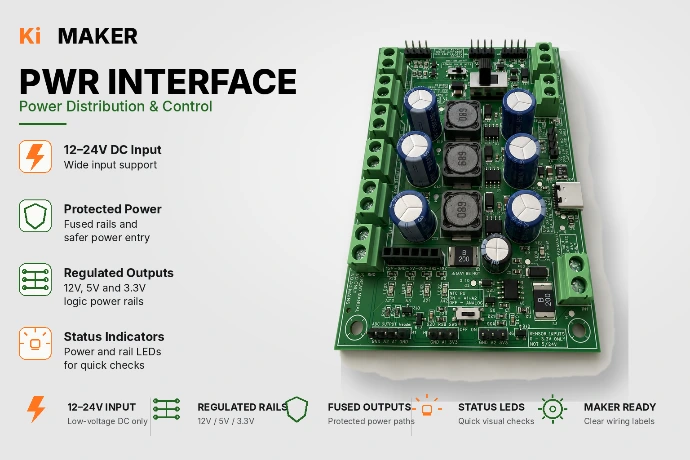
KI Maker PWR INTF Documentation
Power distribution, regulated rails, fan power, USB-C 5 V output, basic utility I/O, and accessory wiring for 18–30 VDC maker systems.
Available downloads:
Owners Manual (pdf)
Specification Sheet
Mechanical Info
Quick Start Guide
Important notes:18–30 VDC input only. USB-C is 5 V output only. IN1/IN2 are dry-contact inputs only. A1/A2 are 0–3.3 V analog/passive NTC input areas only. OUT1/OUT2 are MOSFET low-side outputs and are not isolated relay contacts.
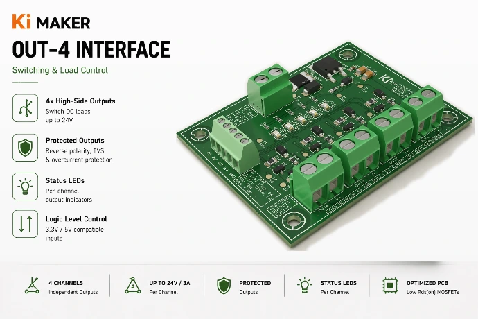
KI Maker OUT-4 Documentation
Protected output control board for switching real-world DC loads from Arduino, ESP32, Raspberry Pi, STM32, and similar controller projects.
Available downloads:
Owners Manual (pdf)
Specification Sheet
Mechanical Info
Quick Start Guide
Typical applications:
LED strips, fans, relays, solenoids, pumps, small motors, and other compatible DC loads
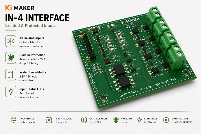
KI Maker IN-4 Documentation
Protected input interface board for connecting external switches, sensors, and field signals to logic-level controller projects.
Available downloads:
Coming Soon!
Typical applications:
Switch inputs, sensor signals, 12/24 V style field inputs, controller input protection, and PLC-style maker projects.