QS-KI-IN4-REVA · Rev-A · KI-IN4 / PCBV1.01
KI Maker IN-4 Quick Start Guide
Quick-start wiring and commissioning guide for the KI Maker IN-4, a 4-channel opto-isolated 9–30 VDC input interface for 3.3 V and 5 V microcontroller and SBC projects. Start with logic power: confirm LED3PWR before applying field voltage.
No AC mains
Field inputs are 9–30 VDC only. NO AC MAINS · LOW VOLTAGE DC ONLY.
Logic header is 3.3 V / 5 V
Never land field voltage on H1. ESP32, Pi, Pico, STM32: 3.3 V VLOGIC. Arduino Uno/Nano may use 5 V.
First power-up
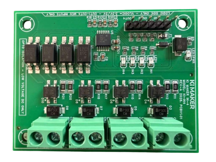
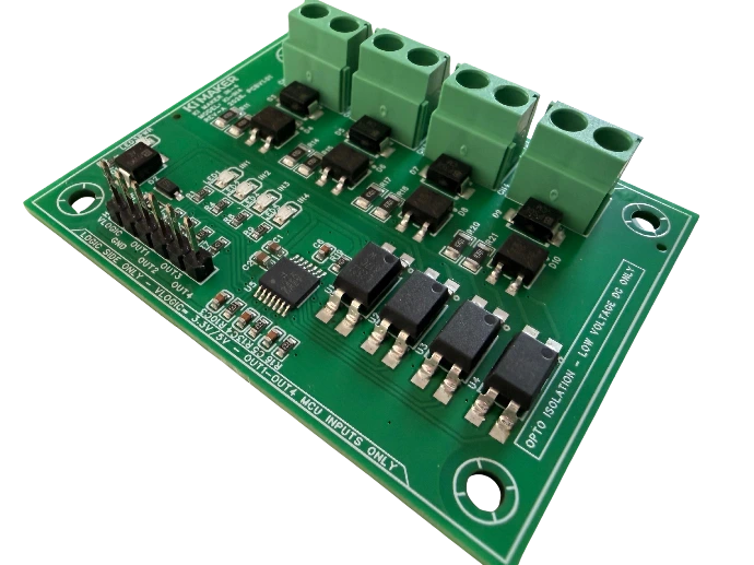
- Mount and inspectFour corner holes. Field terminals on the right (IN1A/B … IN4A/B). Logic header on the left (VLOGIC, GND, OUT1–OUT4).
- Wire logic firstH1 pin 1 (nearest LED3PWR) to 3.3 V or 5 V. Pin 2 to controller GND. LED3PWR should light. If it does not, stop.
- Connect one field pairApply a valid 9–30 VDC field input across CN1 IN1A and IN1B (12 V or 24 V nominal). INxA and INxB are interchangeable. Dry contacts need that DC source in series — IN-4 does not wet the contact.
- Watch LED1Valid field voltage present → LED1 (IN1) on, OUT1 HIGH. Field voltage removed → LED1 off, OUT1 LOW.
- Land OUT1 on a GPIOH1 OUT1 to a controller digital input. Configure the GPIO as a standard digital input with its internal pull-up and pull-down resistors disabled.
- Repeat CN2–CN4All four channels operate independently and may be used simultaneously. Mix 12 V and 24 V as long as each pair stays 9–30 VDC.
Logic header (H1)
Pin 1 is nearest LED3PWR. OUTx is a digital logic output — connect to a controller GPIO. OUTx does not drive loads.
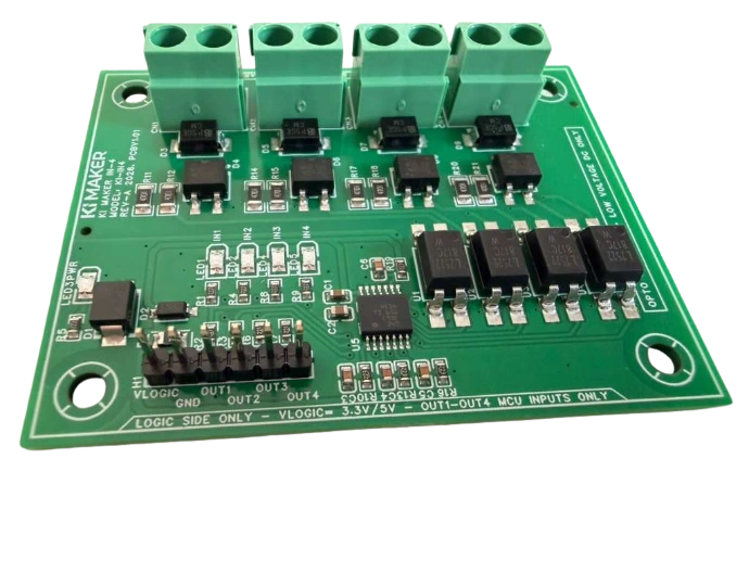
| Pin | Silk | Connect to |
|---|---|---|
| 1 | VLOGIC | Controller 3.3 V or 5 V |
| 2 | GND | Controller GND |
| 3 | OUT1 | GPIO / digital input, channel 1 |
| 4 | OUT2 | GPIO / digital input, channel 2 |
| 5 | OUT3 | GPIO / digital input, channel 3 |
| 6 | OUT4 | GPIO / digital input, channel 4 |
One correct wiring
Dry contact with external 12 V or 24 VDC. IN-4 does not wet the contact.
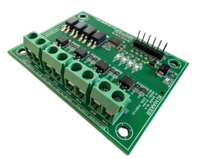
| Connection | Wire |
|---|---|
| External +12 V or +24 V | To one side of the dry contact |
| Other side of contact | INxA |
| 0 V / field return | INxB |
No + / − orientation required
Each input is polarity independent. Reverse the two field wires — the channel still works.
IN-4 documentation
Learn more about the KI Maker IN-4 isolated input board, view the KI Maker documentation library, or download the Quick Start PDF. Owner’s Manual and Specification Sheet are listed on the documentation page as they are released.
Kuster Induction Solutions LLC · KI Maker IN-4 Rev-A · PCBV1.01 · QS-KI-IN4-REVA · Low-voltage DC only · Not a certified safety device or safety-rated isolation barrier.
QS-KI-IN4-REVA · Rev-A · KI-IN4 / PCBV1.01
KI Maker IN-4 Quick Start Guide
Quick-start wiring and commissioning guide for the KI Maker IN-4, a 4-channel opto-isolated 9–30 VDC input interface for 3.3 V and 5 V microcontroller and SBC projects. Start with logic power: confirm LED3PWR before applying field voltage.
No AC mains
Field inputs are 9–30 VDC only. NO AC MAINS · LOW VOLTAGE DC ONLY.
Logic header is 3.3 V / 5 V
Never land field voltage on H1. ESP32, Pi, Pico, STM32: 3.3 V VLOGIC. Arduino Uno/Nano may use 5 V.
First power-up
- Mount and inspectFour corner holes. Field terminals on the right (IN1A/B … IN4A/B). Logic header on the left (VLOGIC, GND, OUT1–OUT4).
- Wire logic firstH1 pin 1 (nearest LED3PWR) to 3.3 V or 5 V. Pin 2 to controller GND. LED3PWR should light. If it does not, stop.
- Connect one field pairApply a valid 9–30 VDC field input across CN1 IN1A and IN1B (12 V or 24 V nominal). INxA and INxB are interchangeable. Dry contacts need that DC source in series — IN-4 does not wet the contact.
- Watch LED1Valid field voltage present → LED1 (IN1) on, OUT1 HIGH. Field voltage removed → LED1 off, OUT1 LOW.
- Land OUT1 on a GPIOH1 OUT1 to a controller digital input. Configure the GPIO as a standard digital input with its internal pull-up and pull-down resistors disabled.
- Repeat CN2–CN4All four channels operate independently and may be used simultaneously. Mix 12 V and 24 V as long as each pair stays 9–30 VDC.
Logic header (H1)
Pin 1 is nearest LED3PWR. OUTx is a digital logic output — connect to a controller GPIO. OUTx does not drive loads.
| Pin | Silk | Connect to |
|---|---|---|
| 1 | VLOGIC | Controller 3.3 V or 5 V |
| 2 | GND | Controller GND |
| 3 | OUT1 | GPIO / digital input, channel 1 |
| 4 | OUT2 | GPIO / digital input, channel 2 |
| 5 | OUT3 | GPIO / digital input, channel 3 |
| 6 | OUT4 | GPIO / digital input, channel 4 |
One correct wiring
Dry contact with external 12 V or 24 VDC. IN-4 does not wet the contact.
| Connection | Wire |
|---|---|
| External +12 V or +24 V | To one side of the dry contact |
| Other side of contact | INxA |
| 0 V / field return | INxB |
No + / − orientation required
Each input is polarity independent. Reverse the two field wires — the channel still works.
IN-4 documentation
Learn more about the KI Maker IN-4 isolated input board, view the KI Maker documentation library, or download the Quick Start PDF. Owner’s Manual and Specification Sheet are listed on the documentation page as they are released.
Kuster Induction Solutions LLC · KI Maker IN-4 Rev-A · PCBV1.01 · QS-KI-IN4-REVA · Low-voltage DC only · Not a certified safety device or safety-rated isolation barrier.