Skip to Content
KI Maker PWR INTF 18 to 30V DC power distribution and controller interface board
KI Maker PWR INTF

Power a 24V controller project from one 18–30V DC supply

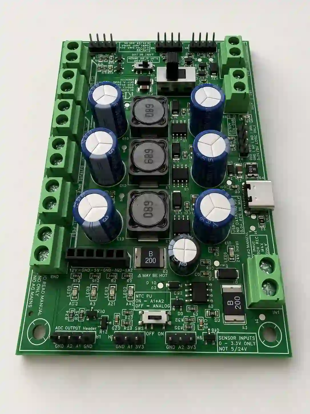
PWR INTF combines regulated 12V, 5V and 3.3V power rails with fused input-voltage distribution and practical controller interfaces. It is designed to replace scattered converters, splitters and loosely labeled wiring in low-voltage automation, test fixtures and maker projects.

  • 18–30V DC main input
  • Regulated 12V, 5V and 3.3V output rails
  • Fused input-voltage distribution rail
  • Fan, low-side output, dry-contact and analog interfaces
  • Clearly labeled screw-terminal connections
$37.50 Available now through the KI Maker eBay store

Ships from Texas · 30-day returns · One-year KI Maker limited warranty · Checkout through eBay

One board, cleaner wiring

What problem does PWR INTF solve?

Many 24V controller projects also need 12V accessories, 5V peripherals and 3.3V logic. Building those rails from separate converter modules creates more connections, more unlabeled wiring and more opportunities for mistakes. PWR INTF centralizes those functions on one documented board.

Use PWR INTF for

  • Arduino, ESP32, STM32 and Raspberry Pi controller projects
  • 24V-powered development benches and test fixtures
  • Projects using 12V fans, sensors or accessories
  • Prototype automation and equipment-monitoring systems
  • Cleaner power distribution from one 24V-class supply
Do not use it as

  • A universal 7–30V input converter—the input range is 18–30V DC
  • A regulated 24V supply—the input-voltage rail follows the main supply
  • A battery charger, inverter or isolated power supply
  • An interface for AC mains voltage
  • A certified safety, emergency-stop or fail-safe controller
Published operating information

Electrical quick reference

This table is a product-selection summary. Read the current specification sheet and owner's manual before wiring the board or applying power.

Function Published specification
Main input 18–30V DC. Low-voltage DC only.
12V regulated rail 12V DC, up to 1.0A within the documented operating and thermal limits.
5V regulated rail 5V DC, up to 1.0A within the documented operating and thermal limits.
3.3V regulated rail 3.3V DC, up to 0.5A within the documented operating and thermal limits.
Input-voltage rail Fused distribution of the applied input voltage. It is not a regulated 24V output.
Fan interface 12V or input-voltage fan supply with PWM and TACH support. Logic pull-up selection supports 3.3V or 5V systems.
Low-side outputs Two onboard low-side MOSFET output channels for compatible low-voltage DC loads. Follow the manual's load limits and wiring.
Digital inputs Two dry-contact inputs. Do not apply external field voltage to these inputs.
Analog inputs Two controller-facing analog channels with a 0–3.3V permitted signal range.
USB-C service connection Documented 5V service function only; it does not replace the 18–30V main input.
Protection Input overcurrent and reverse-polarity protection. Protection devices do not replace correct wiring or an appropriately rated external supply.

Important: the “24V” connection is not a regulated 24V output.

It is fused input-voltage distribution. With 18V applied, that rail is approximately 18V; with 30V applied, it is approximately 30V. Only connect loads rated for the actual applied input voltage.

More than a power splitter

Controller interface functions

Power distribution

Supply regulated 12V, 5V and 3.3V rails while also distributing the fused input voltage to compatible accessories.

Outputs and fan control

Use two low-side output channels and a dedicated PWM/TACH fan interface for documented low-voltage DC loads.

Controller inputs

Connect two dry contacts and two 0–3.3V analog signals without inventing a different connector scheme for every function.

Before applying power

Important operating limits

  • Use only an 18–30V DC main supply.
  • Do not connect AC mains anywhere on the board.
  • The input-voltage rail is fused but not regulated.
  • Do not apply voltage to the two dry-contact input terminals.
  • Do not exceed 3.3V on the controller-facing analog inputs.
  • Observe the documented individual-rail, combined-load and thermal limits.
  • Confirm the fan voltage and logic pull-up selection before connecting a fan or controller.
  • Mount the board on insulated standoffs and protect it from conductive debris.
  • This board does not provide certified galvanic isolation or a safety-rated control function.
Documentation included

Review the wiring and ratings before installation

KI Maker publishes the information needed to evaluate and use PWR INTF. The product-page values are summaries; the current controlled documents remain the detailed reference.

Owner's manual Available
Specification sheet Available
Mechanical information Available
Quick Start guide Available
Application questions

PWR INTF frequently asked questions

Can I power PWR INTF from a 12V supply?

No. The published main-input range is 18–30V DC. A 12V supply is outside the permitted input range.

Does the board generate a regulated 24V output?

No. The input-voltage distribution rail follows the applied main supply and is protected by the input fuse. It is not regulated to 24V.

Can I connect a 24V sensor signal to the dry-contact inputs?

No. IN1 and IN2 are dry-contact inputs and must not receive externally supplied field voltage. Use the KI Maker IN-4 when a controller must monitor 9–30V DC field signals.

Will it work with both 3.3V and 5V controllers?

Yes, when wired according to the documentation. The board provides regulated 3.3V and 5V rails, and the supported logic interfaces are documented for common Arduino, ESP32, STM32 and Raspberry Pi projects.

Can the USB-C connector replace the main DC input?

No. The USB-C connection is limited to its documented 5V service function. Normal board operation requires the specified 18–30V DC main input.

Can I use PWR INTF in a safety or emergency-stop circuit?

No. It is intended for low-voltage electronics, prototypes, test fixtures and general controller projects—not certified safety, emergency-stop, medical or fail-safe applications.

Complete the controller interface

Designed, documented and tested by KI Maker

PWR INTF is developed by KI Maker, a product brand of Kuster Induction Solutions LLC. It is supplied as an assembled, clearly labeled low-voltage controller interface board with published operating limits and supporting documentation.