Skip to Content
KI Maker IN-4 four-channel 9 to 30V optocoupler input module
KI Maker IN-4 · Model KI-IN4

Connect four 12V or 24V DC signals to 3.3V or 5V controller GPIO

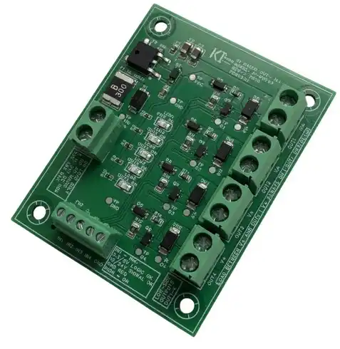
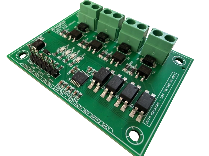
IN-4 converts four independent 9–30V DC field signals into clean, active-high logic outputs for Arduino, ESP32, STM32, Raspberry Pi and similar controllers. Each input uses polarity-independent wiring, an optocoupler and Schmitt-trigger signal conditioning.

  • Four independent 9–30V DC field inputs
  • Polarity-independent two-wire input connections
  • One LTV-817S optocoupler per channel
  • Active-high outputs using a user-supplied 3.3V or 5V VLOGIC rail
  • Per-channel field-input LEDs plus a VLOGIC power indicator
$19.95 Available now · Limited first-production stock

First-production rework disclosure

Reworked and individually function-tested. Minor cosmetic discoloration may be visible near the corrected components. This does not affect electrical performance. Each unit is tested before shipment.

Ships from Texas · 30-day returns · One-year KI Maker limited warranty · Checkout through eBay

Protect the controller interface

What problem does IN-4 solve?

Industrial sensors, PLC outputs, alarm contacts and machine signals commonly operate at 12V or 24V DC, while controller GPIO pins typically operate at only 3.3V or 5V. Those field voltages must never be connected directly to a GPIO pin. IN-4 provides a purpose-built interface between the two voltage domains.

Use IN-4 for

  • 12V and 24V DC sensor-status signals
  • PLC and automation output monitoring
  • Limit switches and relay contacts used with an external DC source
  • Equipment status, alarm and interlock monitoring
  • Automation prototypes, CNC accessories and test fixtures
Do not use it as

  • An analog measurement input
  • A load driver or power output module
  • A source of voltage for a dry contact
  • An AC-mains input or certified isolation barrier
  • A safety, emergency-stop, SIL, PL or fail-safe input
Polarity-independent field inputs

How the inputs work

Connect a 9–30V DC field signal across the corresponding INxA and INxB screw terminals. The onboard bridge rectifier allows either input-wire polarity. When field voltage is present, the channel optocoupler activates and the Schmitt-trigger logic produces a clean HIGH signal at the corresponding OUTx pin.

1. Apply the field signal

Connect the external 9–30V DC signal across the channel's two field-input terminals in either polarity.

2. Isolate and condition

The bridge, protection network, optocoupler and Schmitt-trigger stage convert the field state into a stable logic state.

3. Read the controller output

The matching OUT pin goes HIGH at the supplied VLOGIC level when the field input is active and returns LOW when it is absent.

Field condition Channel LED Corresponding OUTx
No field voltage OFF LOW
9–30V DC present ON HIGH at the supplied VLOGIC level

Never connect field voltage to H1 or directly to a controller GPIO pin.

H1 is the low-voltage logic interface. It accepts only the user-supplied 3.3V or 5V VLOGIC rail, logic ground and the four OUT signals. Field wiring belongs only on the IN1–IN4 screw terminals.

Published operating information

Electrical quick reference

These values are a product-selection summary. Review the current specification sheet and owner's manual for complete wiring, operating and environmental requirements.

Function Published specification
Field inputs Four independent two-wire DC inputs: IN1 through IN4.
Field-input voltage 9–30V DC. Intended for common 12V and 24V DC control signals.
Input polarity Polarity-independent. INxA and INxB may be connected in either DC polarity.
Logic supply User-supplied 3.3V or 5V connected to H1 VLOGIC and logic ground.
Logic outputs OUT1 through OUT4. Active-high digital signals intended for controller GPIO inputs.
Output HIGH level Follows the supplied 3.3V or 5V VLOGIC rail.
Output with no field input LOW.
Field-to-logic isolation One LTV-817S optocoupler per channel provides functional separation between the field and logic signal paths.
Input protection Per-channel bridge rectifier and bidirectional transient-voltage suppression device.
Output conditioning SN74HC14 Schmitt-trigger logic with series output protection.
Connections 5.0mm screw-terminal field inputs and a standard 2.54mm logic header.
Representative verification data

Measured logic-output behavior

The following measurements were recorded on UUT-02 from first-production Lot 2608-01 using the KI Maker PWR INTF R&D board, a JESV supply and a Fluke digital multimeter. They document representative unit behavior; the published limits above remain the product specification.

Test condition OUT1 OUT2 OUT3 OUT4
3.3V VLOGIC, active field inputs 3.262V 3.260V 3.261V 3.258V
5V VLOGIC, active field inputs 4.95V 4.95V 4.95V 4.95V
No field-input voltage, either VLOGIC setting 0V 0V 0V 0V

All reported measurements were stable at the time of observation.

Before applying power

Important operating limits

  • Low-voltage DC field inputs only. Never connect AC mains.
  • Keep every field input within the published 9–30V DC range.
  • Connect only 3.3V or 5V to the H1 VLOGIC pin.
  • Never connect field voltage to H1 or directly to controller GPIO.
  • OUT1–OUT4 are logic signals for controller inputs; they are not load-driving outputs.
  • The board does not supply or “wet” a dry contact; provide an appropriate external DC source.
  • Functional optical separation is not certified safety isolation.
  • Confirm PNP or NPN sensor wiring against the current documentation before applying power.
  • Mount the PCB on insulated standoffs and protect it from conductive debris.
  • Do not use it in medical, life-safety, emergency-stop, SIL, PL or fail-safe applications.
Documentation included

Review the wiring and ratings before installation

KI Maker publishes the information needed to evaluate and use IN-4. The product-page values are summaries; the current controlled documents remain the detailed reference.

Owner's manual Available
Specification sheet Available
Mechanical information Available
Quick Start guide Available
Application questions

IN-4 frequently asked questions

Can IN-4 connect a 24V sensor to an ESP32 or Raspberry Pi?

Yes, when the sensor output and IN-4 are wired within the published 9–30V DC field-input requirements. Supply IN-4 with 3.3V VLOGIC so its active-high outputs match the controller's 3.3V GPIO system.

Can I use 5V Arduino logic?

Yes. Supply the H1 VLOGIC input with 5V and the active OUT signals will follow that logic-supply level.

Does input polarity matter?

No. Each field channel uses a bridge rectifier, so INxA and INxB may be connected in either DC polarity within the published input range.

Can a dry contact be connected directly?

A dry contact does not supply voltage. Use the contact with an appropriate external 9–30V DC source so opening and closing the contact removes or applies voltage across the selected IN-4 channel.

Are OUT1–OUT4 capable of driving relays or solenoids?

No. They are protected logic signals intended for controller GPIO inputs. Use a suitable output driver such as KI Maker OUT-4 for compatible low-voltage DC loads.

Does optocoupler isolation make IN-4 a safety-rated input module?

No. The optocouplers provide functional field-to-logic separation only. IN-4 is not certified for safety, emergency-stop, SIL, PL, medical or fail-safe functions.

Complete the controller interface

Designed, documented and tested by KI Maker

IN-4 is developed by KI Maker, a product brand of Kuster Induction Solutions LLC. It is supplied as an assembled, clearly labeled four-channel field-input interface with published operating limits, supporting documentation and individual functional testing before shipment.