Skip to Content
KI Maker OUT-4 four-channel protected low-side MOSFET output module
KI Maker OUT-4

Switch four 12V or 24V DC loads from low-voltage controller GPIO

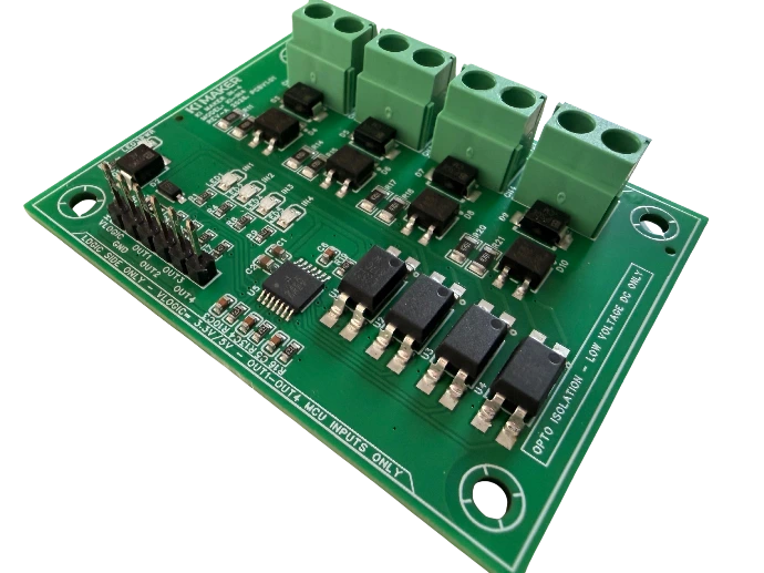
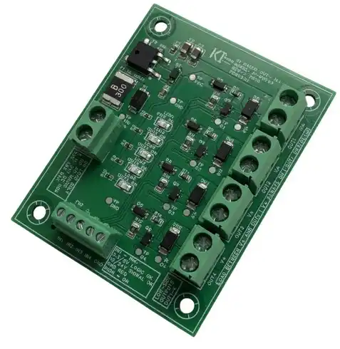
OUT-4 is a four-channel protected low-side MOSFET output module for Arduino, ESP32, STM32, Raspberry Pi and similar controllers. It lets small logic signals control compatible DC loads without asking the controller GPIO pins to supply the load current directly.

  • Four active-high, low-side MOSFET output channels
  • Designed for compatible 12V and 24V DC loads
  • Up to 1.0A on an individual channel, subject to the shared 3.0A board limit
  • 3.3V and 5V controller-compatible logic inputs
  • Per-channel status indication and screw-terminal load connections
$19.95 Available now through the KI Maker eBay store

Ships from Texas · 30-day returns · One-year KI Maker limited warranty · Checkout through eBay

GPIO controls the signal, OUT-4 carries the load

What problem does OUT-4 solve?

A controller GPIO pin is intended to produce a logic signal, not directly power a relay coil, solenoid, valve, fan or 12V/24V lighting load. OUT-4 places a protected MOSFET switching stage between the controller and each load while keeping the wiring and channel status visible.

Use OUT-4 for

  • Compatible 12V and 24V relays and contactors
  • Solenoids, pneumatic valves and small DC actuators
  • LED strips, indicator lamps and other resistive DC loads
  • Small DC fans and controller accessories
  • Automation prototypes, test fixtures, CNC accessories and robotics
Do not use it as

  • An isolated relay board—the controller and load sides share ground
  • A high-side switch or dry-contact output
  • A motor-direction controller or H-bridge
  • A load power supply or voltage converter
  • An interface for AC mains or safety-rated switching
Low-side switching

How the outputs work

Connect the positive side of each load to its appropriately rated external 12V or 24V DC supply. Connect the negative side of the load to the corresponding OUT terminal. When the matching controller input is HIGH, the MOSFET switches the OUT terminal toward ground and the load turns on.

1. Supply the load

Use an external low-voltage DC supply that matches the load voltage and can provide the required current.

2. Share ground

Connect controller ground, OUT-4 logic ground and load-supply negative as specified in the wiring documentation.

3. Drive the input

A controller HIGH signal commands the corresponding low-side output and illuminates its status indicator.

OUT-4 sinks current; it does not source load voltage.

The positive side of the load remains connected to its external DC supply. OUT-4 switches the load's return path. The board does not create 12V or 24V and does not provide galvanic isolation.

Published operating information

Electrical quick reference

These values are a product-selection summary. Review the current specification sheet and owner's manual for complete wiring, simultaneous-load and operating-temperature requirements.

Function Published specification
Number of channels Four independent low-side MOSFET output channels: OUT1 through OUT4.
Load applications Compatible 12V and 24V DC loads. Low-voltage DC only.
Channel current Up to 1.0A on an individual channel, subject to the shared board-current and simultaneous-load limits.
Total board current 3.0A maximum shared across all active channels. Four equally loaded channels must therefore remain at or below 0.75A per channel.
Logic inputs Four controller-compatible active-high inputs for 3.3V or 5V GPIO systems.
Output topology Non-isolated N-channel MOSFET low-side switching. Load and controller grounds must be connected as documented.
Output state Logic input HIGH commands the corresponding output ON; logic input LOW commands it OFF.
Protection Shared input overcurrent protection plus onboard transient and MOSFET-gate protection. Protection does not replace correct load sizing and wiring.
Status indication Individual visual status indication for each commanded output channel.
Connections Screw-terminal load connections and clearly labeled controller interface connections.

The 3.0A limit is shared by the complete board.

“Up to 1.0A per channel” does not mean four channels may each carry 1.0A simultaneously. The total continuous current through the board must remain within 3.0A and all published thermal limits.

Before connecting a load

Important operating limits

  • Low-voltage DC loads only. Never connect AC mains.
  • Do not exceed 1.0A on any individual output channel.
  • Do not exceed 3.0A total across all simultaneously active channels.
  • Confirm the load's steady-state, startup, inrush and stall current before connection.
  • Use an external supply matched to the load voltage; OUT-4 does not power the load by itself.
  • Connect the required common ground before applying controller logic signals.
  • The outputs are not isolated, floating or potential-free contacts.
  • Do not use OUT-4 for bidirectional motor control, braking or polarity reversal.
  • Mount the PCB on insulated standoffs and protect it from conductive debris.
  • Do not use it in medical, life-safety, emergency-stop or fail-safe applications.
Documentation included

Review the wiring and ratings before installation

KI Maker publishes the information needed to evaluate and use OUT-4. The product-page values are summaries; the current controlled documents remain the detailed reference.

Owner's manual Available
Specification sheet Available
Mechanical information Available
Quick Start guide Available
Application questions

OUT-4 frequently asked questions

Can an Arduino, ESP32, STM32 or Raspberry Pi drive OUT-4?

OUT-4 is designed for controller-compatible 3.3V and 5V active-high logic signals when wired according to the documentation. The controller commands the MOSFET; it does not supply the load current.

Can all four outputs carry 1.0A at the same time?

No. The board has a shared 3.0A total-current limit. With four equally loaded channels active, each channel must remain at or below 0.75A, subject to the documented thermal conditions.

Does OUT-4 provide 12V or 24V to the loads?

No. The loads require an external DC supply. OUT-4 is a low-side switching interface and controls the return path to ground.

Are the four outputs electrically isolated?

No. OUT-4 is a non-isolated MOSFET output board and requires the controller and load circuit to share the documented ground reference.

Can it reverse a DC motor?

No. OUT-4 provides one-direction low-side switching. Motor reversal and electronic braking require an appropriately rated H-bridge or motor controller.

Can I switch an inductive load?

Compatible low-voltage DC inductive loads may be used within the published voltage, current, transient and thermal limits. Verify startup or inrush current and follow the current manual's wiring requirements.

Complete the controller interface

Designed, documented and tested by KI Maker

OUT-4 is developed by KI Maker, a product brand of Kuster Induction Solutions LLC. It is supplied as an assembled, clearly labeled low-voltage output-interface board with published operating limits and supporting documentation.