QS-KI-PWRINTF-REVB · Rev-B · KI-MPB-RevB / PCBV1.02
PWR INTF Quick Start Guide
In seven steps
Power the board, verify the rails, then connect one load or controller function at a time.
- 18–30 VDC input
- 24 V fused path
- 12 V / 5 V / 3.3 V regulated rails
- USB-C 5 V output only
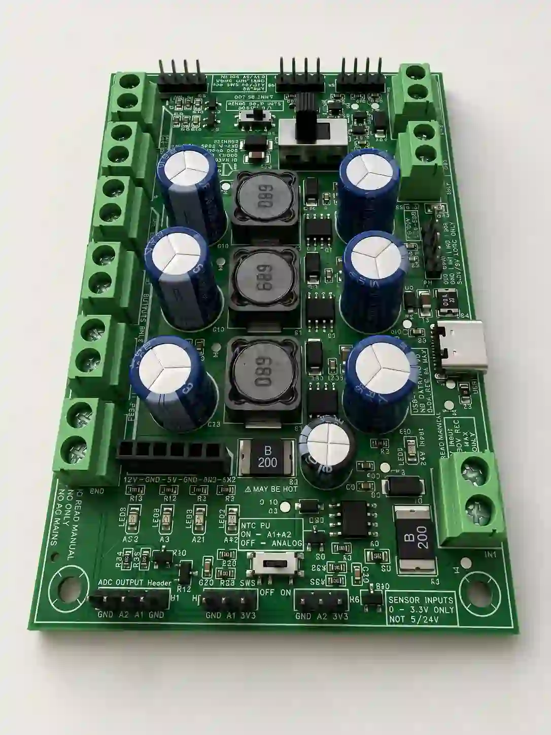
Read before power-up
- Use 18–30 VDC input only. No AC mains anywhere on the board.
- USB-C is a 5 V output only. Do not power the board from USB-C.
- IN1 / IN2 are dry-contact / switch-to-ground inputs only. Do not apply external voltage.
- A1 / A2 and sensor inputs are 0–3.3 V only.
- OUT1 / OUT2 are low-side MOSFET outputs, not floating relay contacts.
5-minute first power-up
- Mount the boardInsulated M3 standoffs. Keep the bottom side away from conductive surfaces, loose hardware, and debris.
- Leave everything else offControllers, sensors, and loads stay disconnected for the first power-up.
- Set the fan selectorIf you will use a fan later, set 12 V or 24 V before power-up.
- Land the supply18–30 VDC on the main input with correct polarity. 24 V nominal is the expected use case.
- Watch the rail LEDsLED1 24 V input · LED2 24 V fused out · LED3 12 V · LED4 5 V · LED5 3.3 V.
- Measure the railsConfirm 24 V, 12 V, 5 V, and 3.3 V before connecting anything else.
- Add one thing at a timeOne controller signal or one load, then re-check voltage and temperature.
Expected first-use result
No unusual smell, noise, or hot spot. Rail LEDs on. Measured rails present. Then move to one basic hookup.
Most important wiring rule
OUT1 / OUT2 are low-side switches
Connect the load positive wire to the matching positive rail and the load negative wire to OUT1 or OUT2.
Do not wire OUT1 / OUT2 like floating relay contacts. Do not backfeed any rail from another power source.
Connector groups
| Group | Quick use |
|---|---|
| Main input | 18–30 VDC only. Check polarity before power-up. |
| 24 V / OUT1 / IN1 | 24 V accessory path and low-side switched OUT1. Up to 1.0 A continuous. |
| 12 V / OUT2 / IN2 | 12 V rail and low-side switched OUT2. Shares the 12 V rail budget. |
| 5 V / 3.3 V | Controller and logic/sensor supply. 5 V 1.0 A · 3.3 V 0.5 A. |
| USB-C | 5 V output only, 0.5 A max. Not a power input, not data, not USB-PD. |
| IN1 / IN2 SW | Dry-contact / switch-to-ground only. No external voltage. |
| A1 / A2 / Sensor | 0–3.3 V analog or passive NTC only. |
| Fan header | Selectable 12 V / 24 V fan power with PWM / TACH. |
Switches — set before power-up
| Switch | Quick use |
|---|---|
| Fan selector | 12 V or 24 V fan power output. |
| I/O pull-up | Tach and SW inputs pull-up, 3.3 V or 5 V. |
| Analog | On = A1+A2. Off = analog header path. |
Released ratings
Continuous, open air. Do not assume every rail can run at maximum at the same time.
| Rail / output | Limit |
|---|---|
| Main input | 18–30 VDC only (24 V nominal expected) |
| OUT1 / 24 V path | Up to 1.0 A continuous |
| OUT2 / 12 V path | Up to 1.0 A continuous (shares 12 V rail budget) |
| 5 V rail | 1.0 A continuous |
| 3.3 V rail | 0.5 A continuous |
| USB-C output | 5 V output only, 0.5 A max |
Thermal / airflow
For OUT1 / OUT2 loads above 500 mA, verify board temperature during first use. Cooling is recommended near maximum current, especially in an enclosure.
Stop immediately if…
- You are not sure about polarity, connector identity, or whether a signal is dry-contact or voltage-based.
- A rail reads incorrectly, an LED pattern seems wrong, or a component becomes unexpectedly hot.
- You are about to connect 5 V, 12 V, 24 V, FAN_V, VIN, or USB-C VBUS into A1, A2, IN1, IN2, or the sensor header.
What to read next
Kuster Induction Solutions LLC · KI Maker PWR INTF Rev-B · PCBV1.02 · QS-KI-PWRINTF-REVB · Low-voltage DC only · Not for AC mains, life-safety, medical, or certified safety systems.
QS-KI-PWRINTF-REVB · Rev-B · KI-MPB-RevB / PCBV1.02
PWR INTF Quick Start Guide
In seven steps
Power the board, verify the rails, then connect one load or controller function at a time.
- 18–30 VDC input
- 24 V fused path
- 12 V / 5 V / 3.3 V regulated rails
- USB-C 5 V output only
Read before power-up
- Use 18–30 VDC input only. No AC mains anywhere on the board.
- USB-C is a 5 V output only. Do not power the board from USB-C.
- IN1 / IN2 are dry-contact / switch-to-ground inputs only. Do not apply external voltage.
- A1 / A2 and sensor inputs are 0–3.3 V only.
- OUT1 / OUT2 are low-side MOSFET outputs, not floating relay contacts.
5-minute first power-up
- Mount the boardInsulated M3 standoffs. Keep the bottom side away from conductive surfaces, loose hardware, and debris.
- Leave everything else offControllers, sensors, and loads stay disconnected for the first power-up.
- Set the fan selectorIf you will use a fan later, set 12 V or 24 V before power-up.
- Land the supply18–30 VDC on the main input with correct polarity. 24 V nominal is the expected use case.
- Watch the rail LEDsLED1 24 V input · LED2 24 V fused out · LED3 12 V · LED4 5 V · LED5 3.3 V.
- Measure the railsConfirm 24 V, 12 V, 5 V, and 3.3 V before connecting anything else.
- Add one thing at a timeOne controller signal or one load, then re-check voltage and temperature.
Expected first-use result
No unusual smell, noise, or hot spot. Rail LEDs on. Measured rails present. Then move to one basic hookup.
Most important wiring rule
OUT1 / OUT2 are low-side switches
Connect the load positive wire to the matching positive rail and the load negative wire to OUT1 or OUT2.
Do not wire OUT1 / OUT2 like floating relay contacts. Do not backfeed any rail from another power source.
Connector groups
| Group | Quick use |
|---|---|
| Main input | 18–30 VDC only. Check polarity before power-up. |
| 24 V / OUT1 / IN1 | 24 V accessory path and low-side switched OUT1. Up to 1.0 A continuous. |
| 12 V / OUT2 / IN2 | 12 V rail and low-side switched OUT2. Shares the 12 V rail budget. |
| 5 V / 3.3 V | Controller and logic/sensor supply. 5 V 1.0 A · 3.3 V 0.5 A. |
| USB-C | 5 V output only, 0.5 A max. Not a power input, not data, not USB-PD. |
| IN1 / IN2 SW | Dry-contact / switch-to-ground only. No external voltage. |
| A1 / A2 / Sensor | 0–3.3 V analog or passive NTC only. |
| Fan header | Selectable 12 V / 24 V fan power with PWM / TACH. |
Switches — set before power-up
| Switch | Quick use |
|---|---|
| Fan selector | 12 V or 24 V fan power output. |
| I/O pull-up | Tach and SW inputs pull-up, 3.3 V or 5 V. |
| Analog | On = A1+A2. Off = analog header path. |
Released ratings
Continuous, open air. Do not assume every rail can run at maximum at the same time.
| Rail / output | Limit |
|---|---|
| Main input | 18–30 VDC only (24 V nominal expected) |
| OUT1 / 24 V path | Up to 1.0 A continuous |
| OUT2 / 12 V path | Up to 1.0 A continuous (shares 12 V rail budget) |
| 5 V rail | 1.0 A continuous |
| 3.3 V rail | 0.5 A continuous |
| USB-C output | 5 V output only, 0.5 A max |
Thermal / airflow
For OUT1 / OUT2 loads above 500 mA, verify board temperature during first use. Cooling is recommended near maximum current, especially in an enclosure.
Stop immediately if…
- You are not sure about polarity, connector identity, or whether a signal is dry-contact or voltage-based.
- A rail reads incorrectly, an LED pattern seems wrong, or a component becomes unexpectedly hot.
- You are about to connect 5 V, 12 V, 24 V, FAN_V, VIN, or USB-C VBUS into A1, A2, IN1, IN2, or the sensor header.
What to read next
Kuster Induction Solutions LLC · KI Maker PWR INTF Rev-B · PCBV1.02 · QS-KI-PWRINTF-REVB · Low-voltage DC only · Not for AC mains, life-safety, medical, or certified safety systems.